Optical Comms
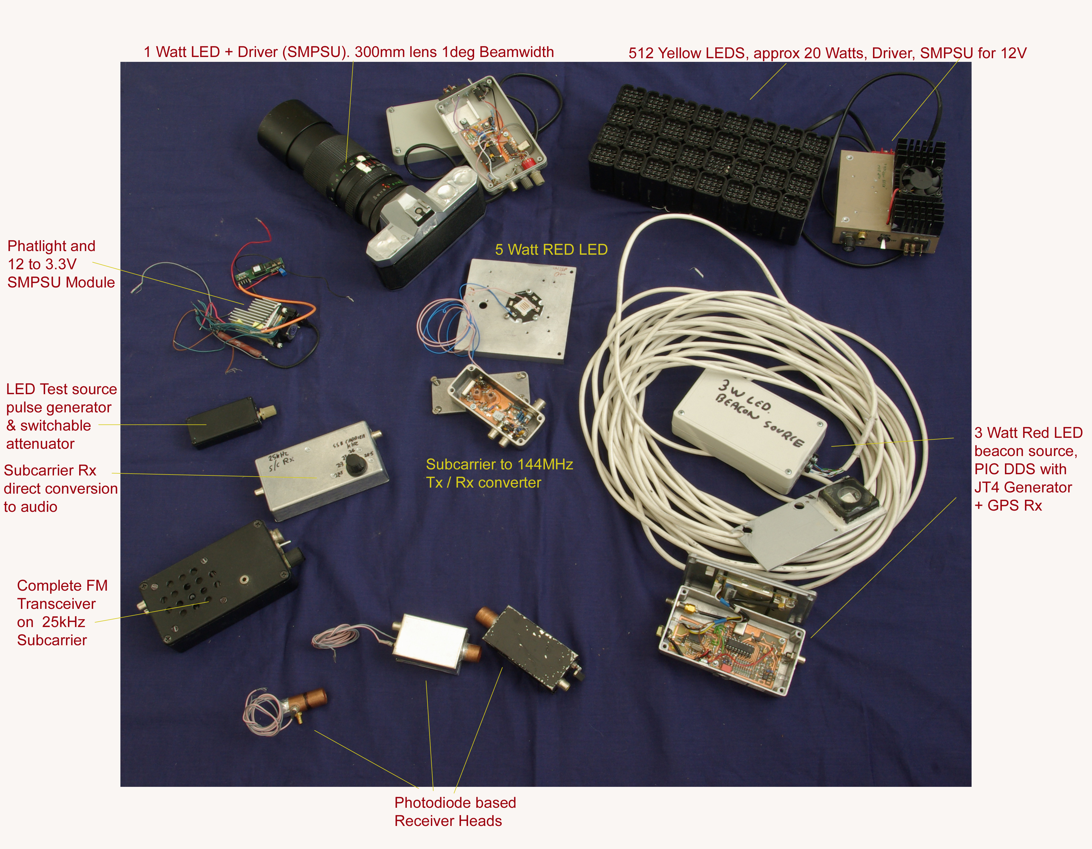
Items for sale. Most are described below
So much for transmitter sources
A Constant current drive and modulator for the 1 Watt LED uses the circuit shown , allowing tone modulation at a couple
of subcarrier frequencies and also an audio tone, with a basic square wave modulation. Also, and of more use in the future, a connection for an
external modulation input allowing linear current modulation of the LED up to around 95% modulation.
That was Transmitters Sorted
But again, the "two of everything" rule took hold, so how about a 25kHz standalone FM transceiver. This shows the
circuit diagram of one made with junkbox components. The transmitter uses the VCO from a 4046, an idea taken from the RadCom article.
The receiver is based around an XR2211 modem chip. Several were in the junk box, although they can still be found in the Farnell and RS catalogues and the
chip makes an excellent FM receiver. It has a hard limiter coping with input levels down to 2mV, and the PLL demodulator is designed specifically for
coping with large relative bandwidth signals. 3kHz deviation FM on a 15 - 25kHz subcarrier is quite a lot! Demod parameters are set by selecting values
of two resistors and two capacitors. The design procedure is beautifully and precisely detailed in the data sheet.
Considerable discussion on the UKNanowaves Group centred on sensitivity of detector heads and the relative merits of baseband vs. subcarrier schemes.
There was a feeling initially that sensitivity fell off above just a few kHz - a belief probably down to he fact that the output level rolls off
considerably. Using the SDR-IQ and a LED connected to the output of a tunable oscillator, It was shown that while gain / output level does indeed
fall off - the Signal to Noise ratio remains remarkably constant up to frequencies of at least 30kHz.
In fact, it is more-likely that the rapidly falling gain leads to the degradation in S/N above these frequencies due to increasing second
stage noise contribution. The first set of measurements are
OptRxFreqresponse.pdf and a second more precisely controlled set of results
OptRxFreqresponse_2.pdf
All of which show that, in terms of receive sensitivity alone, there seems to be no difference between the two.
Other Odds and Ends
A simple beacon using a 3 Watt wide beamwidth LED A PIC is used as a low frequency DDS to deliver two tones
alternately. I chose 25000 and 24800Hz alternating at 0.2 second for a distinctive audio note when receiving on an SSB receiver.
For a simple high sensitivity SSB / CW transceive capability, this 144MHz Transverter, is designed for use
with the favourite rig of many microwave ops: the IC202 transceiver. The LO comes from an off-the-shelf 48MHz TTL oscillator module, tripled.
A DBM is used for Tx and Rx frequency conversion with an attenuator to drop the the 1 Watt down to a level suitable for driving the mixer.
The attenuator is left in circuit on Rx as there is ample gain in the optical Rx head to overcome the additional loss.
The DC level present on the IC202 antenna port controls Tx/Rx switching.
The WSJT weak signal modes have been used successfully by VK7MO and others for cloud scatter
Most Items are now for sale - contact me andy.g4jnt@gmail.com if you are interested in any item and would like ot make an offer
The 2011 Yorkshire Microwave Roundtable at Finningley (which is not actually in Yorkshire!) had a couple of talks on Optical Communications.
After listening to these talks and re-reading the article in March - May's 2011 RadCom by G8CYW, my interest in building something was triggered:
 LEDs have become the norm now, with operation moving away from lasers. Modern high power LEDs, with relatively simple optics
can generate sub-degree beamwidths, at ERPs comparable with laser pointer type transmitters. This makes them simpler to aim, removes
scintillation effects and is more politically acceptable than shining lasers over the countryside. So, on hearing about the
Farnell 1 Watt 20 degree beamwidth LED, I bought a couple.
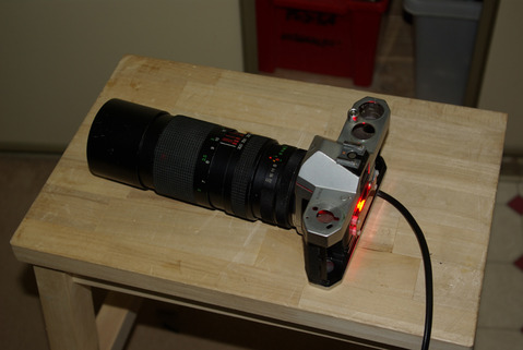
An ancient Pentax mechanical camera was stripped to provide the mount for an old 100-300mm zoom lens.
The 1 Watt LED was mounted at the focal plane - where the shutter used to go - on a copper plate as a heatsink. A 1 degree beamwidth
resulted when the lens was set to max focal length.
LEDs have become the norm now, with operation moving away from lasers. Modern high power LEDs, with relatively simple optics
can generate sub-degree beamwidths, at ERPs comparable with laser pointer type transmitters. This makes them simpler to aim, removes
scintillation effects and is more politically acceptable than shining lasers over the countryside. So, on hearing about the
Farnell 1 Watt 20 degree beamwidth LED, I bought a couple.
An ancient Pentax mechanical camera was stripped to provide the mount for an old 100-300mm zoom lens.
The 1 Watt LED was mounted at the focal plane - where the shutter used to go - on a copper plate as a heatsink. A 1 degree beamwidth
resulted when the lens was set to max focal length.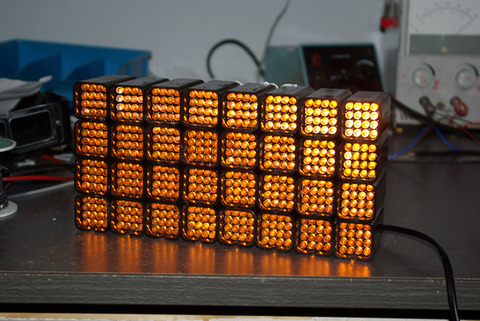 I also had a solid block made up of 512 Yellow LEDs taken from one character of a motorway sign. Each Pixel of the 7x5 dot matrix array
consists of a module of 16 LEDs running off 24V. 32 of these pixel modules were glued together into a brick-sized assembly with all the
drive lines commoned. When running from the specified 24V, current consumption is around 1 Amp
I also had a solid block made up of 512 Yellow LEDs taken from one character of a motorway sign. Each Pixel of the 7x5 dot matrix array
consists of a module of 16 LEDs running off 24V. 32 of these pixel modules were glued together into a brick-sized assembly with all the
drive lines commoned. When running from the specified 24V, current consumption is around 1 Amp
A similar circuit, but with the switch mode module PSU delivering 28 Volts was built to drive the Yellow Brick
 The RadCom article flagged up a high sensitivity receiver head amplifier for use with a PIN-Photodiode, using a rather novel hybrid J-FET + bipolar
cascode design with separately defined and optimised drain and collector currents. It is derived from one by Clint KA7OEI. --
So I built up a simplified version using components found in the junk box (2N3819 & BC107 instead of the semiconductors specified). It worked fine
with a junk box SH2030 photodiode. Wanting to build two of everything,
and having no more 2N3819 devices, I designed this P-Channel FET version of the head amp which gave just about
the same performance with a BPW34 photodiode. (A second NE5532 stage with a gain of 40 was subsequently added to match the signal levels from the original head amp)
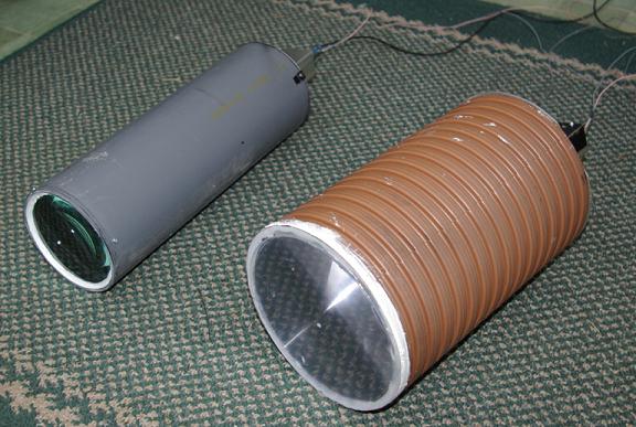
Both head amps were built into screened tinplate boxes with a short length of 15mm water pipe to mate with the optics.
The RadCom article flagged up a high sensitivity receiver head amplifier for use with a PIN-Photodiode, using a rather novel hybrid J-FET + bipolar
cascode design with separately defined and optimised drain and collector currents. It is derived from one by Clint KA7OEI. --
So I built up a simplified version using components found in the junk box (2N3819 & BC107 instead of the semiconductors specified). It worked fine
with a junk box SH2030 photodiode. Wanting to build two of everything,
and having no more 2N3819 devices, I designed this P-Channel FET version of the head amp which gave just about
the same performance with a BPW34 photodiode. (A second NE5532 stage with a gain of 40 was subsequently added to match the signal levels from the original head amp)
Both head amps were built into screened tinplate boxes with a short length of 15mm water pipe to mate with the optics.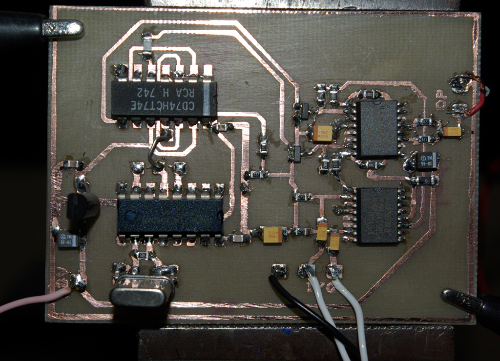 I had always intended using the SDR-IQ (which tunes down to 500Hz) as the receiver for all practical operating, allowing maximum sensitivity for weak
signal working. But it would need a transmitter or two for linear modes. This simple quadrature
upconverter was built to translate the I/Q outputs from either an SDR2GO baseband transceiver or from a PC soundcard up to a suitable
subcarrier frequency for SSB and datamode operations.
I had always intended using the SDR-IQ (which tunes down to 500Hz) as the receiver for all practical operating, allowing maximum sensitivity for weak
signal working. But it would need a transmitter or two for linear modes. This simple quadrature
upconverter was built to translate the I/Q outputs from either an SDR2GO baseband transceiver or from a PC soundcard up to a suitable
subcarrier frequency for SSB and datamode operations.
PIC Code can be found here .
G0HNW made a similar beacon source using 1000Hz and 15000Hz tones for both baseband and subcarrier type reception.
This PIC based LF DDS Beacon Source is actually made up from two modules
each using a 16F627 or 16F628 device. One takes in timing information from a GPS receiver and generates the frequency
codes for each symbol. These go via a three wire serial interface to the second device that implements a low frequency DDS.
The two modules work together to generate a modulated subcarrier at a frequency up to around 25kHz. PIC code for JT4, JT65 and WSPR
modes can be installed. For JT65 and JT4 switch selection of the variants with different frequency spacings is possible.
As an alternative for short duration testing (a few hours) there are versions of each code generator that do not need GPS timing but
instead rely on the PIC crystal oscillator free running.
Each module could be used individually for other purposes. Full details are in the
Full Download Archive  Wide angle high power LEDs can be used in transmitters with simple optics by adding a short focal length lens immediately in front of the LED.
Barry G8AGN characterised such use with a PMN lens. Suitable elements can be found by ripping apart old 50mm SLR lenses. The necessary high curvature
elements with typically 28mm focal length can be found in the middle - used to shorten the physical length of the camera lens.
Wide angle high power LEDs can be used in transmitters with simple optics by adding a short focal length lens immediately in front of the LED.
Barry G8AGN characterised such use with a PMN lens. Suitable elements can be found by ripping apart old 50mm SLR lenses. The necessary high curvature
elements with typically 28mm focal length can be found in the middle - used to shorten the physical length of the camera lens.