The Rebuilt GB3SCS
GB3SCS was the last of the Bell Hill beacons to be converted for frequency locked operation. The 3.4 to 10GHz beacons had already been converted to GPS locking using the reverse DDS approach SCC_Locking.htm and the time had come to do the 2.3GHz beacon as well, and to add a datamode waveform to the transmission similar to that on the 10GHz beacon GB3SCX JT4_GB3SCX.pdf A number of users had also noticed that GB3SCS’s power was down, although we didn’t know that at first.
RF Source
Just for the sake-of-it, this beacon was going to be different – it wouldn’t just duplicate the same frequency locking used on the others. I had just been given by M0EYT a salvaged PCB from a wireless networking system that had several synthesizers on it. All were good quality units based around an LMX2326 chip and Z-Comm packaged VCO and when programmed from a controller to load in the appropriate frequency setting data worked well. They were separated from the main PCB with a hacksaw. One was found to operate at 2.3GHz and looked as if it might form the basis of the RF source for a new beacon.
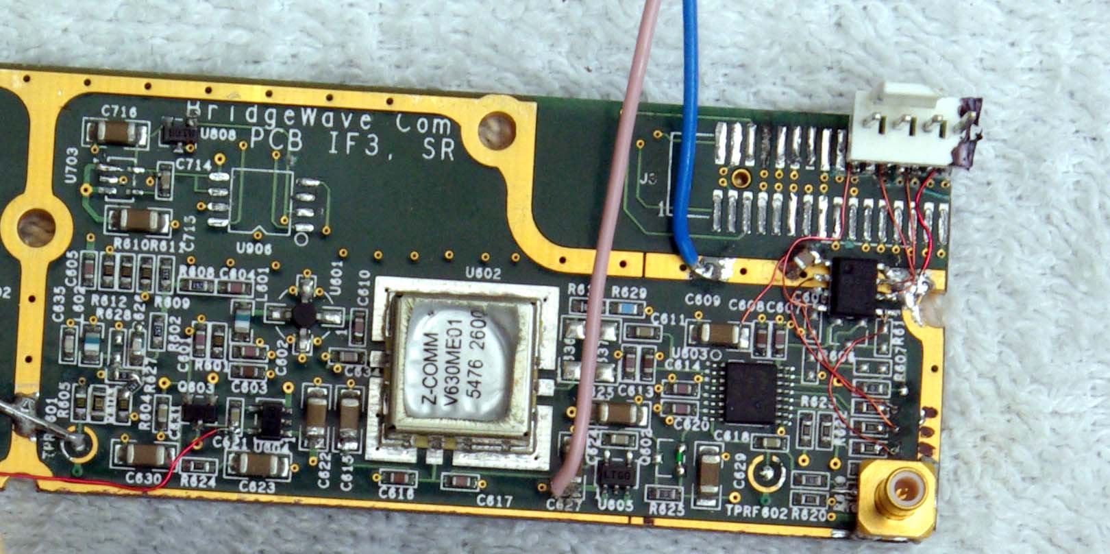
It was decided to use the PLL as a multiplier and generate the input from an AD9852 DDS module, donated by G0API. The PLL can multiply by the ratio of integers, N / R and even with the comparison frequency kept high at a few hundred kHz in order to maintain a high loop bandwidth to keep close in phase noise down, still gives plenty of scope for choosing optimum values of R and N for the DDS drive. The DDS was directly clocked from the 10MHz reference and initially the intention was to use the AD9852 without its internal PLL clock multiplier, meaning that the output frequency to drive the synthesizer would have to be below 3MHz.
To start with, a convenient multiplication factor of 1000 was selected for the PLL which was driven from the DDS at 2.320905MHz (PLL dividers R = 5 and N = 5000 with a comparison frequency of 464kHz). On the first test of the complete source, the sidebands were horrendous, extending out to several kHz either side of the carrier, and the concept would have been unworkable. However, by setting he DDS clock multiplier to give 40MHz, ie setting its PLL for *4 )the lowest value possible without bypassing the multiplier altogether) the output was cleaned up considerably. DDS sidebands get multiplied by the frequency multiplication process, and what may start out as an apparently clean signal can become quite dirty when multiplied by 1000 times. As a rule of thumb, sidebands increase with the square of the multiplication, so *1000 theoretically represents a 60dB increase in their level. The PLL cleans-up those sidebands separated by more than the loop bandwidth away, but can do nothing about close in ones – they have to be dealt with from first principles, usually involving choice of frequency and clock.
One set of sidebands from the DDS remained, spaced at 17kHz at a level of only -26dBc; still not really acceptable. So the search went on for another choice of frequency that gave lower DDS sidebands. Several were tried, and in general frequencies that were well=away from a simple subdivision of 10MHz were cleanest. Also, those closer to 3MHz were somewhat better than around 2MHz – a slightly unexpected finding, but DDSs are fickle devices when it comes to calculating their spurii.
Then the thought ran to using a crystal filter, as we’d used at 72MHz for the 144MHz beacon GB3VHF to filter out spurii close in to the carrier. What low cost off-the-shelf crystal in the 2 – 3MHz region could be pressed into use here? A very simple filter could made just by putting a crystal in series with the 50 ohm feed from DDS to PLL provided the series resonant frequency was suitable. Initially a 2MHz crystal was tried as I had several. The series resonance was measured as 1.9997MHz, and with a bit of number crunching in a spreadsheet DDS&PLL.xls , it was found that with the PLL set for R = 5, N = 5803 (effective multiplication 1160.4) a drive of 1.999746MHz could be used – within the measured filter response. However, this frequency was found to generate an unfortunate set of very close in sidebands from the DDS that even the crystal filter couldn’t get rid of sufficiently. This is what sometimes happens when a DDS is used very close to a subharmonic of the clock.
So… look for another crystal frequency… back to the spreadsheet. The well known baud-rate 2.4576MHz means associated crystals cost pennies, so one was tested. This time it appeared to be specified as series resonant as the response peaked at 2.45768MHz; With R = 6 and N = 5666 (effective multiplication 944.333) the DDS now had to generate 2.457718MHz for 2320.905MHz output – just about within the filter passband. With these values all programmed in, the worst case sidebands were now at +/-37kHz at a level of -55dBc. (Without the crystal filter, some closer in ones were observed, in the -45dB region)
Data Transmission
The PIC controller on the DDS takes in UTC data from the GPS receiver along with a one pulse-per-second signal indicating the UTC reference. The PIC was programmed to generate a JT4G waveform from pre-stored symbol data by sending frequency data to the DDS in real time. The complete beacon message format consists of JT4G sent on the even minute, which takes about 48 seconds, followed immediately by callsign and locator. The CW data is repeated at the odd minute plus 30 second point. At all other times the beacon sends plain carrier at the JT4G lowest Tone-0 frequency defined at 2320.905000MHz.
New Power Amplifier
Then the real problems started.
After we recovered the hardware from the Hill, a functional test showed no power output from the beacon; it was giving a few tens of milliwatts, sufficient for a report or two from semi-locals, but certainly not the 1 Watt it was giving when originally commissioned. The RF2126 PA had died (although it was still consuming the correct current from its supply). After playing with these chips to try to use two combined, I got an uncomfortable feeling about them and decided not to pursue this route. An appeal on the UK Microwaves Reflector resulted in an offer from G7LWT of a ‘Heli-Telly’ PA.
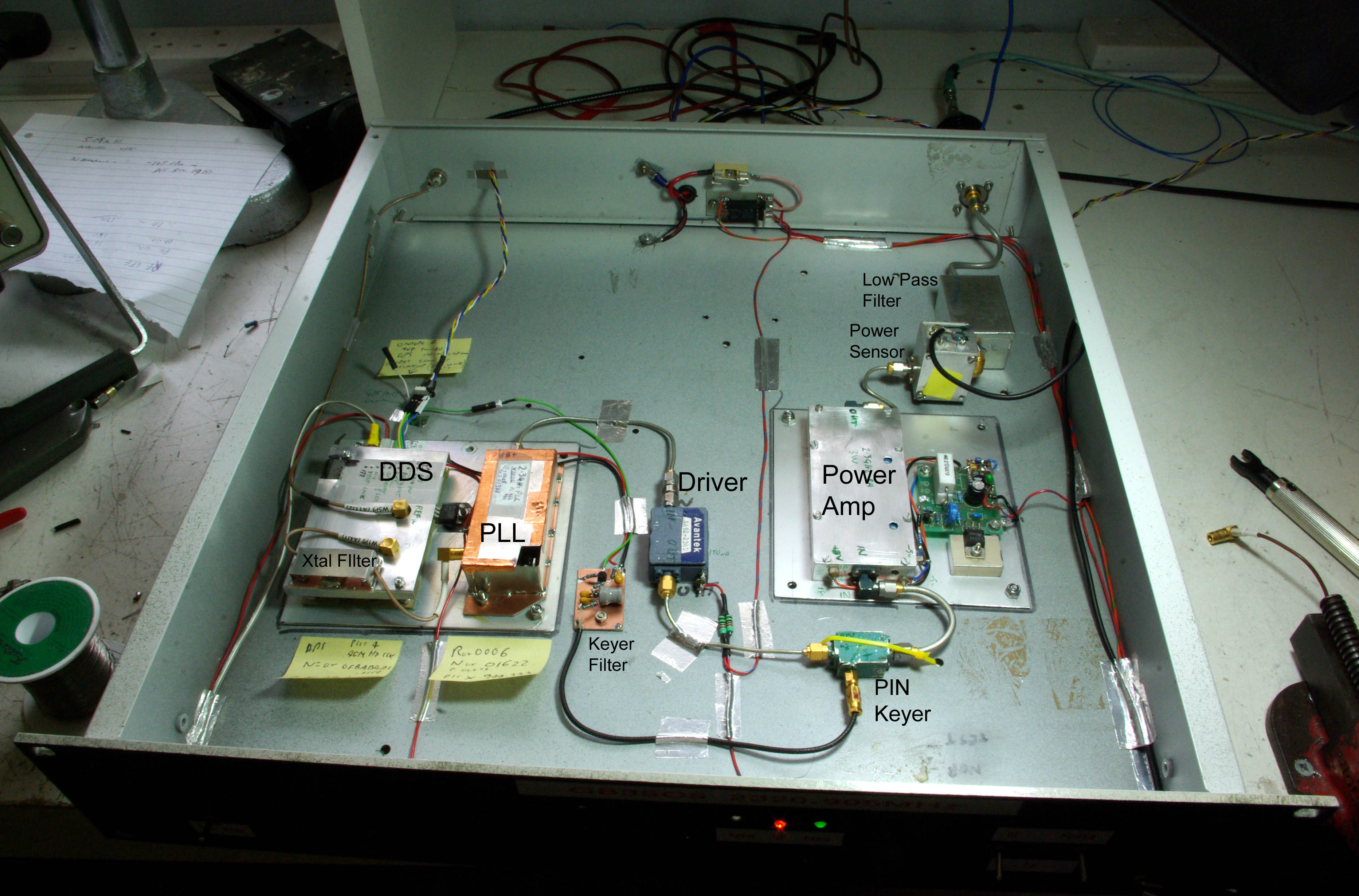
After a round-about delivery route via the RSGB convention at Wyboston and G4LFM, this unit turned out to consist of a non-working high power output stage (which would probably have been too much for the Bell Hill power supply capability anyway) preceded by a JE1AAH 3 Watt driver stage with associated power conditioner. The driver module was ideal, just the sort of power increase we were looking for and well within Bell Hill PSU capability. There was also a useful PCB Low Pass Filter that was recovered, put into its own tinplate box with SMA connectors and used as a final harmonic filter. The remaining touch was to add a directional coupler diode detector in a connectorised small module that I had spare for an on-site power monitor / test point.
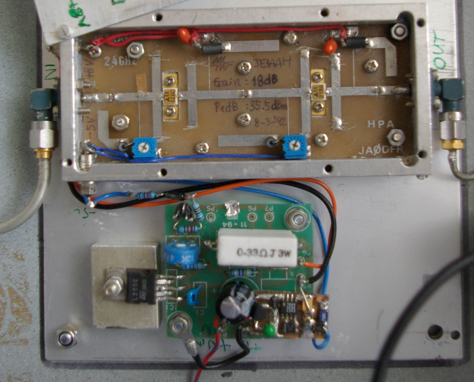
The PA needed +19 to +20dBm for full output while running into slight compression, and this could conveniently come from an old Avantek amplifier module sitting surplus in the junk box. With more than 20dB gain a 10dB attenuator was added between the PLL module delivering +8dBm and the input to ensure the driver was running just into a couple of dB of compression.
The remaining task was to add the CW keying. All the Bell Hill beacons use on-off CW for their identification and this would have to follow the same route. The PIC DDS controller delivers a TTL level signal, and on all the other beacons this is taken to the frequency multiplier stages which offer a convenient point for switching the RF. With just two amplifier modules in the way, neither of which could be keyed easily, a separate RF switch was needed. Again, a rummage through the junk box solved the problem A microwave PIN diode switch was found, which with 6mA flowing into the control connection gave 45dB attenuation at 2GHz. (All those little odd rally purchases become useful, eventually – never be tempted to throw anything away!) The TTL level signal from the PIC needed to be inverted, and although this could have been done in software it was decided to build a proper buffer and add a simple L/C filter to slow down the rise and fall times to prevent key clicks. An opamp filter could have been used, but LC was simpler, and suitable components were to hand (see note re junkbox, above).
The Complete Assembly