GB3SCC is locked to a 10MHz GPS derived reference in the same manner as that for GB3SCX and GB3SCF. The crystal
oscillator that had originally been part of the DB6NT RF source generating the RF was removed and the X48 multiplier adapted
to accept an external input at 120MHz. The existing crystal was incorporated into a separate VCXO by including it witha series varicap diode into a Butler oscillator. A 74AC04 high speed CMOS logic IC
was used as an output buffer for the VCXO.
PLL Design
Modulation
Construction
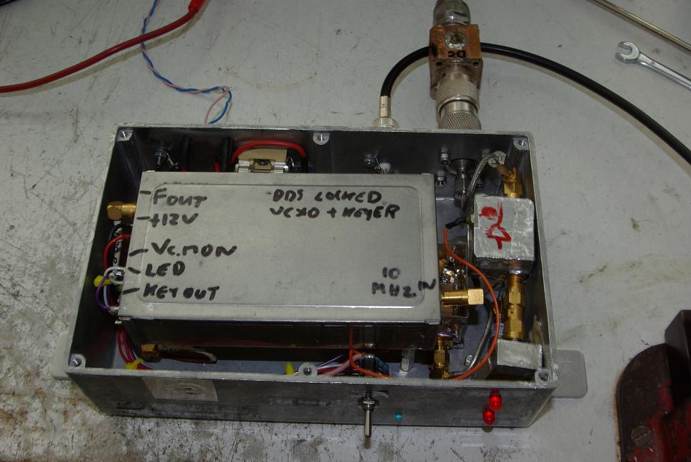
To avoid major restructuring of the beacon hardware, the new frequency locking module was supported on
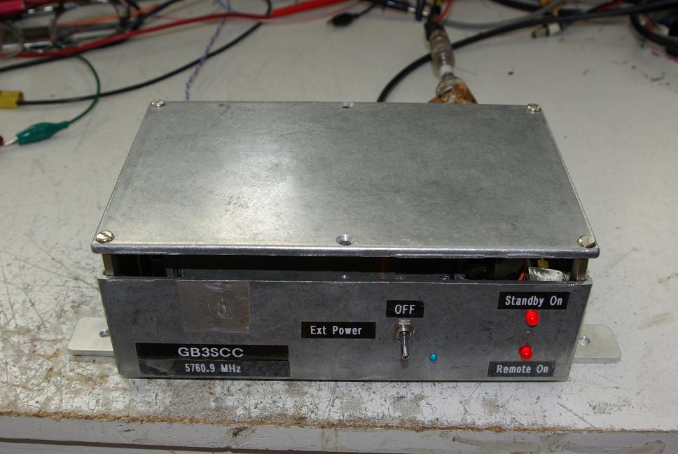
pillars above the RF multiplier. A view Inside the box shows the
construction. The complete Packaged Driver can be seen here. Note
how the lid of the diecast box had to be mounted on spacers to accommodate the additional locking module.
Testing
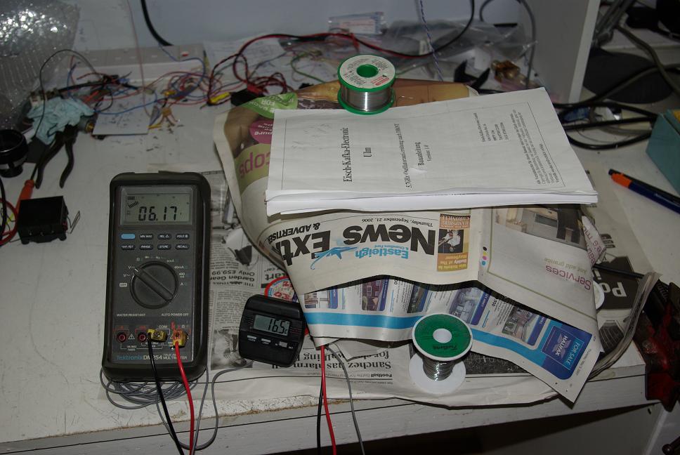
The lower temperature limit was generated by sandwiching the unit in two freezer packs and wrapping in newspaper.
as can be seen in the Cold Test. The lowest temperature obtained by this method
inside the box was 12C which is probably around the value that would occur with an external temperature of about 3C - 5C.
The final part of the test regimen was a long duration soak-test. The unit was set up in my shed running for over
a week continuously, while monitoring the power output on a diode power meter. The frequency and keying performance was checked by listening to the radiated signal on my 5.76GHz Rx converter in the shack in the house. The 10MHz reference was delivered on a coax cable from the shack master frequency standard.
The output amplitude stayed remarkably constant over the test and no glitches were detected in the PLL performance. At this point it was returned to service on Bell Hill.
One output from the buffer drives the X48 multiplier to generate the final output frequency and another output
becomes the clock signal for an AD9851 DDS. The DDS is programmed to generate 10MHz when clocked at exactly
the right frequency for the wanted beacon signal (at 5760.905MHz when multiplied up). The 10MHz DDS output
goes to the input of an NE612 mixer chip, whose LO input comes from the GPS derived 10MHz reference.
The resulting output voltage from the the mixer is amplified in an op-amp and applied to the varicap, adjusting the crystal
oscillator to give a Phase Locked Loop that keeps the crystal on exactly the right frequency. In
actual fact, the finite frequency resolution of the DDS (32 bit setting accuracy, or 1 part in 4 billion)
means the final output frequency is a few Hertz in error. LckdSrcs.pdf
gives more detail and includes a circuit diagram.
The pulling range of the VCXO is a few hundred Hertz for a voltage swing of 2 to 9V and the VCXO sensitivity for this particular unit showed a remarkably linear 120Hz /Volt over this the range.
The combinatin of NE612 mixer and voltage gain in the op-amp gave a phase detector sensitivity of around 3V / radian. Taking these figures in conjunction with the effective division ratio of 12 in the DDS that generates 10MHz from 120MHz, the
PLL natural frequency can be shown to be about 40Hz. This gives an upper limit to the loop bandwidth.
Synthesizers generally want the maximum loop bandwidth possible, and at the comparison frequency of 10MHz,
which cannot pass through the loop control circuitry, we can safely say that no significant additional
loop-filter is necessary.
The crystal had originally been specified for 60C operation and used with a clip-on crystal heater. ALthough
the crystal does not now have to remain stable over temperature as it merely forms the resonator for a VCO, the heater was kept to ensure the crystal did not drift outside its lock range. The loop bandwidth of around 40Hz was narrower
than in previous versions of this locking circuit used inteh other beacons, so a bit more care had to be taken over locking and pull-in range.
Previous versions of this PLL had sufficient loop bandwidth to pass FSK RTTY and fast DFCWi keying. The lower
bandwidth on this one meant that only DFCWi was really practical as a modulation type, and even the 50ms intersymbol gap as used for GB3SCX sounded 'wrong'. So simpler DFCWi with no intersymbol gap was chosen; Symbol length was set at 500ms, the same as GB3SCX.
The earlier locked sources had used separate PIC controllers for setting the DDS to one of several stored spot frequencies controlled by signal input lines, with the actual CW and DFCW or RTTY data coming from a separate keyer module.
GB3SCC adopted a more compact solution with a single PIC on the DDS board doing both functions. As the on-off keying for the normal CW is performed by hard switching the RF stages, an output line had to be provided from the PIC to the RF module for this.
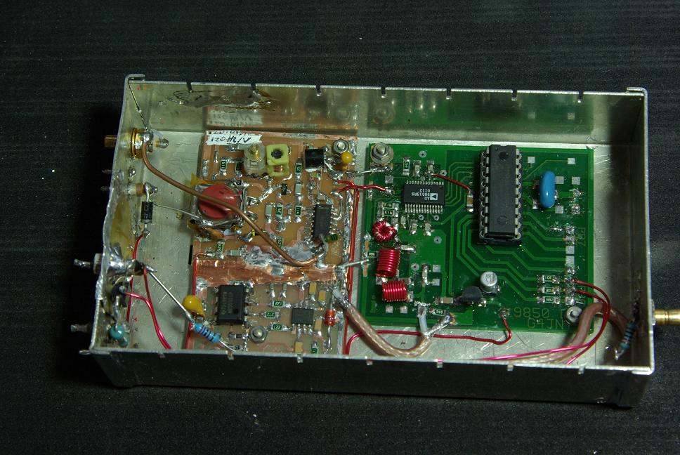
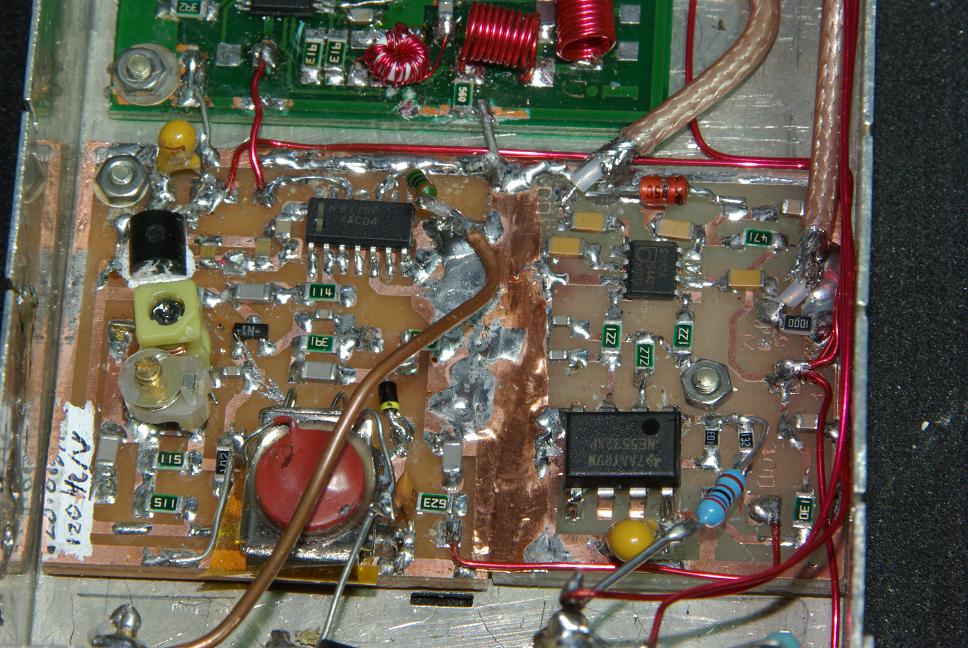
The various bits of circuitry needed for the PLL were constructed as three separate
modules that were already designed and had been used on GB3SCF and 'X. : A VCXO module, a mixer/op-amp and the DDS
source which can be seen in this photograph of the three modules in their separate enclosure.
The VCXO and PLL boards can be seen in more detail here
The low loop bandwidth and resulting pull-in range meant that more attention had to be paid to ensuring
the PLL remained locked under all conditions - mainly over temperature extremes. The complete source unit was tested over
a range of temperatures that exceeded those likely to be encountered in the cabin on Bell Hill. Fortunately
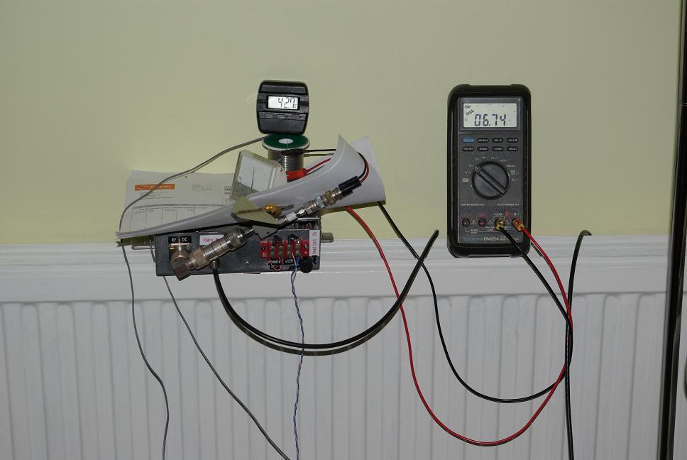
several years worth of telemetry logging showed the values that have been observed there, and that are likely to be encountered in the future, ie. a range of 8C to 32C inside the cabin. To simulate hot conditions the unit was placed on a central heating radiator and the heating turned up high (all radiators in the rest of the house were turned off !)
A view of the Hot Testing. A digital thermometer probe was placed inside
the diecast box, here it is showing 42C, but in fact the upper limit reached was 47C
The PLL control voltage was monitored over temperature and stayed comfortably within a volt or so of the middle of its
range, around 6V. So temperature is not an issue.
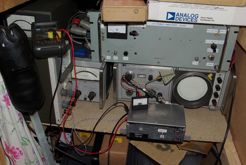
A photo of the Soak Testing shows the additional items of test equipment needed.
(Note the 8410 Network Analyser is not part of the test, it just lives in the shed!). As the output of the source
also carries power for the beacon head amplifier, a DC block is needed while testing - this is a surplus unit in N-type connectors and can be seen on the right-angled connector at the rear of teh diecast box. Then follows a two way splitter, with one arm going to a diode detector / meter for monitoring power output, and the other to a small antenna radiating up to my shack.