A simple way of phase locking microwave local
oscillators.
Andy Talbot G4JNT
This article was first published in the Microwave Newsletter April 2004
In the article on ‘Locked Oscillator Sources for Microwave Use’ published in the March Microwave Newsletter, I made the throwaway comment in the first paragraph that phase locking local oscillators with nice round frequencies of integer MHz was simpler than producing an arbitrary value for beacons etc. Well, after saying that I had to come up with something and here are a few notes on a simple breadboard method of phase locking these crystal oscillators to a reference source. The circuit is presented as a starting point - there will be some experimentation needed for each individual case.
For the popular microwave bands the LOs are usually generated from overtone crystal oscillators followed by multipliers, with the following table showing the usual LO frequencies for the narrowband segments along with the associated crystal frequency. The final columns show the highest frequency that is a submultiple of both this and a 10MHz reference, the highest common factor or HCF, and the associated division. This HCF can become the comparison frequency in a phase locked loop, and is the highest frequency that is possible here.
|
Band |
IF |
LO |
RF Mult |
Crystal |
Division N |
HCF (kHz) for 10MHz Fref |
Division R |
|
1296 |
144 |
1152 |
12 |
96.00000 |
96 |
1000.00 * |
10 |
|
1296 |
28 |
1268 |
12 |
105.66667 |
317 |
333.333 |
30 |
|
2320 |
144 |
2176 |
24 |
90.666667 |
136 |
666.667 |
15 |
|
3400 |
144 |
3256 |
36 |
90.444444 |
407 |
222.222 |
45 |
|
5760 |
144 |
5616 |
54 |
104.00000 |
104 |
1000.00 * |
10 |
|
10368 |
144 |
10224 |
96 |
106.50000 |
213 |
500.000 |
20 |
|
10368 |
144 |
10224 |
108 |
94.666667 |
142 |
666.666 |
15 |
|
24048 |
144 |
23904 |
240 |
99.600000 |
249 |
400.000 |
25 |
|
24048 |
432 |
23616 |
240 |
98.400000 |
246 |
400.000 * |
25 |
|
47088 |
144 |
46944 |
432 |
108.66667 |
163 |
666.666 |
15 |
|
47088 |
432 |
46656 |
432 |
108.00000 |
108 |
1000.00 * |
10 |
Two things become obvious:
All the comparison frequencies can be derived from a 10MHz reference by making use of simple logic divider chips to give the divide by R function (all could be derived from 2MHz in fact)
All the comparison frequencies are over 200kHz, so phase locked loops can be made with wide loop bandwidths. For those marked with a *, an even higher comparison frequency is possible, but the values stated keep the frequencies within a narrower band for a common design. So now the only difficulty is providing the divide by N from the crystal frequency. An off the shelf synthesiser chip such as the MC145170, or those from other manufacturers, would make an easy job of this but there is an even simpler solution providing you are prepared to do a bit more adjustment and optimisation.
Anyone who has studied the ‘brick’ range of microwave sources will have seen how a high Q cavity oscillator is locked to a reference oscillator in the 100MHz region by a sampling phase detector. This device combines the functions of frequency multiplier and phase in one network. In the bricks, a snap varactor diode is hit with about 200mW of reference signal and so generates sharp sub-nanosecond pulses at this rate. These pulses are applied across a pair of microwave diodes, forming one input to a single balanced mixer whose other RF ports is fed with a portion of the cavity oscillator signal picked off via a small probe.
This sampling mixer approach to PLL design makes for considerable simplicity as it inherently removes any need for a high frequency divide by N circuit - but has two major drawbacks. Firstly, the VCO can lock to ANY harmonic of the reference, and in the brick designs this is prevented by restricting the electrical tuning range of the VCO to less than half of the comparison frequency - sometimes a pull in range of only 5 - 10MHz (at the fundamental L-Band frequency) can be observed. Secondly, the output from the phase detector is at a very low level - typically a few tens of millivolts per radian rather than the 1.6V/radian of normal logic. In effect, the complete voltage range that would have been possible for the drive power is having to be shared over every one of the comb frequencies. However, a low noise op-amp can easily provide DC gains of the hundred or so required here, and differential amp doing this job inside the bricks is clearly visible when the side cover is removed.
So, lets try this idea at lower frequencies to lock a VCXO - the very restricted tuning range of crystal oscillators means that drawback 1 is not an issue. Look at the circuit of Figure 1, a two chip R divider (programmable for any value from 1 to 256) generates the reference. This is applied to an impulse generator using the propagation delay inherent in three high speed logic gates plus an additional capacitor to generate a series of negative going impulses of a few nanoseconds in width. If you look at the output at this point on a spectrum analyser, the spectrum will show the classic sin(x)/x shape with a null corresponding to the pulse width. The extra 100pF capacitor in the delay can be adjusted to ensure this null does not fall at the wanted crystal frequency - it can get a bit unpleasantly close with 74AC series gates in this position.
These impulses are at a level sufficient to directly drive a diode ring mixer, so all that is now necessary is to apply a portion of the VCXO to the other mixer port, amplify and filter the IF output and feed back to the VCXO for a complete PLL. As in all the microwave sources I’ve discussed so far, the PLL needs to have as wide a bandwidth as possible to remove VCXO close in phase noise and jitter, so there is not much effort that has to go into filtering, apart from removing the fundamental comparison frequency component. This last point is significant, don’t go too low with the reference frequency as filtering it out will be more difficult, as well as the fact that the voltage swing available from the diode ring will be even less.
The pair of 74HC161 devices forming the R divider could be replaced by appropriate sections of a 74HC390 chip, or an ‘HC90 with feedback in some cases, but this solution gives a generalised divider allowing factors for R divisions not in the table, such as those with 7, 11, or 27 in them that couldn’t be obtained from a simple configuration. It works be preloading in the number set on the links, then counting up to 256 where it overflows and loads in the preset value again repeating the process. So, the wire links have to be configured to load in a value of (256 - R). With HC CMOS, a logic ‘1’ must not be generated by leaving an input as an open circuit, as could be done in the old days of TTL (and even then it was unethical!), so each input must be tied to either +5V or ground.
Results.
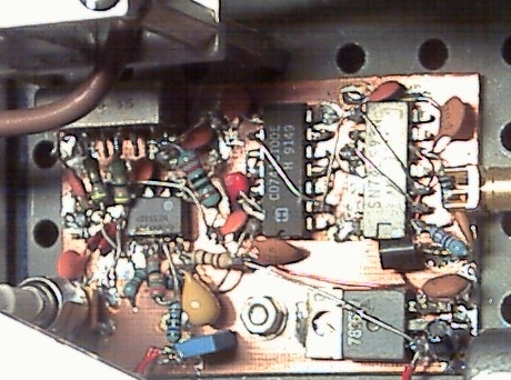
My breadboard was not exactly as
shown in Figure 1. Instead, I started
off with a 1MHz signal rather than 10MHz and divided by 3 in a single chip to
give 333.333kHz which was used to lock the 94.666MHz crystal in my ‘JVL based
10GHz system as shown in Figure 2. The breadboard for this proof-of-concept can be seen Here
Figure 1 has been built, and just committed to PCB, but not yet
into any finalised system. The first
version for 10GHz worked fine, except for the fact that the VCXO drive level to
the mixer was rather critical - this has to be kept at about 1mW for the mixer
to remain linear, whilst maximising the DC output level from the IF. If drive level is increased too much, the
mixer saturates and, surprisingly, IF
output falls off in this usage. I’m not
too sure why this should happen, but is probably due to the short pulse forming
the pseudo-LO, and its very low means value.
Real experimenters may like to try replacing the packaged DBM with a
pair of diodes plus transformer/balun for a single balanced design as in the
bricks. This may give more sensitivity
and less dependence on RF drive level, but I couldn’t be bothered with this
level of fine tuning once the DBM had proved itself.
Note that the mixer also has to be one where both sides of the IF port are accessible. Most devices like the SRA-1 and SBL-1 offer this, but higher frequency mixers sometimes ground one side of the IF so in this event the op-amp will need to cope with a negative input voltage. The DC gain in the OP-amp circuitry is what was required for this 333kHz reference - other higher comparison frequencies will allow proportionately lower gains. The exact circuit configuration is not a completely true differential amplifier as this is not essential, it also has to transfer the 5V reference through to the output. As true differential operation is not necessary, to change the gain it is only really necessary to alter the single resistor shown as 330k in Figure 1. An easy way to set up the necessary DC gain is to look at the op-amp output on a scope with both reference and VCXO signal applied, but with the input to the VCXO tuning diode clamped to the 5V centre value. Then by manually tuning the VCXO through its range a beat at the difference frequency will be seen, this will be centred on exactly 5 Volts and its peak to peak value must be wide enough to be able to tune the VCXO at all ranges of temperature and drift - a value of 2 - 5 volts peak-to-peak will probably suffice for most VCXO designs. The op amp gain may need adjusting to get to this figure, and the value also depends to some extent on the RF level to the mixer. With no reference applied, the VCXO needs to be adjusted to the wanted frequency with 5V on its tuning line - try to get as close as possible as the tuning range is not very wide once temperature and crystal ageing are taken into account.
My breadboard locks up near instantly when connecting the reference - provided the crystal heater has been pre-warmed! If a crystal heater is used, the initial cold start frequency will probably be outside the PLL lock range; in my case it takes about 10 seconds for warm-up before the PLL will lock from a cold start.
Now, the only drawback to getting within 0.1Hz on my 10GHz system (and yes, I can get 10-11 on the reference) is the accuracy of the 144MHz IF. The IC202 LO is derived from a DDS (more about this another day) controlled from a bog-standard packaged 100MHz crystal oscillator and rotary up-down counter plus LCD display to 10Hz resolution and 100Hz readout. The DDS could have been driven from the 10MHz reference multiplied up, but there is still the inherent accuracy of the carrier crystal inside the IC202, so I can only get to within tens of Hz of the wanted frequency at 144MHz without doing some pre-calibration of the IF, and even then it will drift a few more Hz over the day. When I designed the digital IC202 LO I hadn’t anticipated wanting a better accuracy for microwaves than this, but some recent tests between G8ACE and G3NNS make this assumption invalid now …