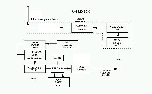
A decision was made early on, that if it was worthwhile having a 24GHz beacon then it would also be useful to have it as a stable reference source. Signals are difficult enough to find on the band without having to guess the frequency too. If the receiving station is also locked to a standard [3] or Adret, or has accurate frequency calibration then it should almost be a case of pointing the antenna and listening!! The beacon frequency was thus to be locked to an ovened 5MHz frequency standard. A number of approaches where considered. However the design shown in the accompanying block diagram finally crystallised when a 12GHz "brick" with 96 MHz reference input was kindly donated to the project.
Initially the task of generating the 95.4321627MHz reference frequency for the brick was to have been by a Pye HS400 source but a neater and more compact solution using the WA6CGR synth was decided upon. A full description of this module is given in the WA6CGR web site [1]. Suffice to say that M and N values for the synth. of 914 and 835 were selected using the basic program also available. This equates to having a difference IF frequency in the synth. for frequency comparison purposes of 4.567833MHz. After initial problems relating to the SBL-1 mixer levels and products, the WA6CGR circuit proved successful. Final frequency trim in the order of tens of Hz at 5MHz is performed using the slight variation allowable on the ovened reference, the only part eventually used from the HS400. At first the scheme was to use a VCXO with a xtal at 96MHz as part of the loop, but this proved unreliable as lock couldn't be consistently achieved, thus a VCXO using a 11.92MHz xtal and multiplication to 95MHz, in a scheme similar to that used in the JNT MSF standard source [3] was eventually designed in, with very reliable locking.
Keying of the VCXO, to produce F1 keying proved very poor, which was perhaps to be expected and upset the stability of the loop despite adjustment of the loop time constants to compensate and it was eventually decided to adopt A1 key by PIN diode keying of the drive to the 12GHz amplifier. The main advantage of this being that it leaves the main frequency determining section of the beacon untouched and thus stability is not impaired. This has resulted in minimal pulling of frequency and a pleasant keying characteristic, but does have the slight disadvantage of having a "spacer" wave about 20dB down, due to 12GHz feed-thro' through the amplifier in the "off" state...but at anything less than an S9+ signal is not noticeable.
Electrical implementation of the unit at the mast head was intriguing, as it was decided not to have the weighty "brick" in the head unit, and to give it the benefit of the temperature controlled environment of the equipment bunker. Thus only the 24GHz circuits are located at the head unit. This does mean feeding 12GHz up the mast and this was accomplished by using 1/2" LDF4-50 heliax. Despite the heliax being out of spec. at this frequency, the signal emerges to drive the 12/24GHz multiplier at +10dBm. To produce a reasonable signal of 500mW a"surplus" Toshiba amplifier module is used. This in practise gives an output of 800mW into the antenna. 12 volt power to the head unit is also directed up the coax in a similar manner to GB3SCX.
To house the "indoor unit", a 2U 19" rack mount shelf including mains power supply is used in the equipment room for the bulk of the equipment including the synth., brick, keyer PSU etc. The head unit containing all the 24GHz circuits is mounted in a diescast box with a lid seal and heatsink Since power consumption of the power module is ~5W it was thought that heat dissipation might be a problem, but with the power module bolted to the box wall and an external heatsink, the temperature rise is minimal. A temperature sensitive switch is provided to cut the 12V supply should the box temperature in very hot weather, rise above 70deg C. A small length of PTFE tube acting as a radome for the omni slotted waveguide antenna. The antenna itself is based on a design in Dubus 1/1984 by DK2VR.
Latest Upgrade, October 2013. The beacon has been updated to send JT4G. An RDDS module was donated by G8ACE and the hardware changed to use this. The RDDS is fed with the 11.92MHz signal from the VCXO which locks it to 2.5MHz divided down from the 5MHz on board reference. NMEA Timing data for JT4G generation is supplied from a GPS receiver.
As with all the BH beacons, Tone 0 of the JT4G is placed on the beacon's nominal carrier, 24048.905MHz so correct tuning is achieved with an SSB carrier reference 800Hz lower at 24048.9042MHz
Photos of the Beacon Hardware
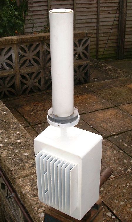
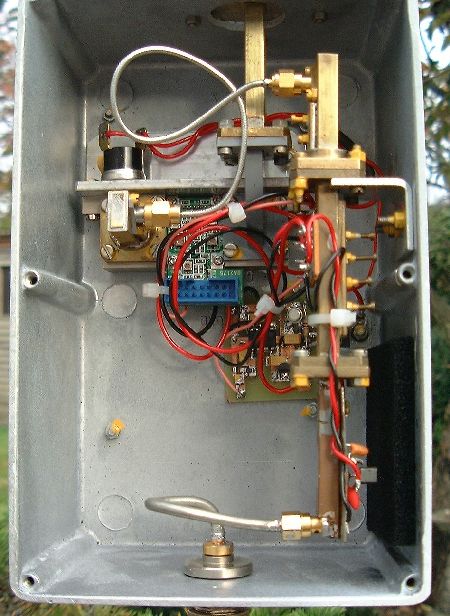
The photos above show the head unit hardware for the GB3SCK 500mW beacon, comprising the DB6NT doubler and waveguide filter on the right and bolted to the base of the box, the Toshiba amplifier module. The whole unit is enclosed in a waterproof diecast box with a PTFE radome covering the slotted waveguide antenna shown above.
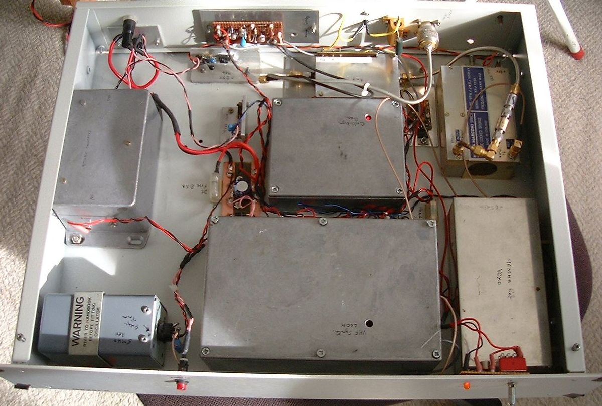
This picture shows the "indoor unit" with the SM power supply, the CWID keyer, 5MHz reference oscillator and the phase locked loops and the microwave "brick" PLL.