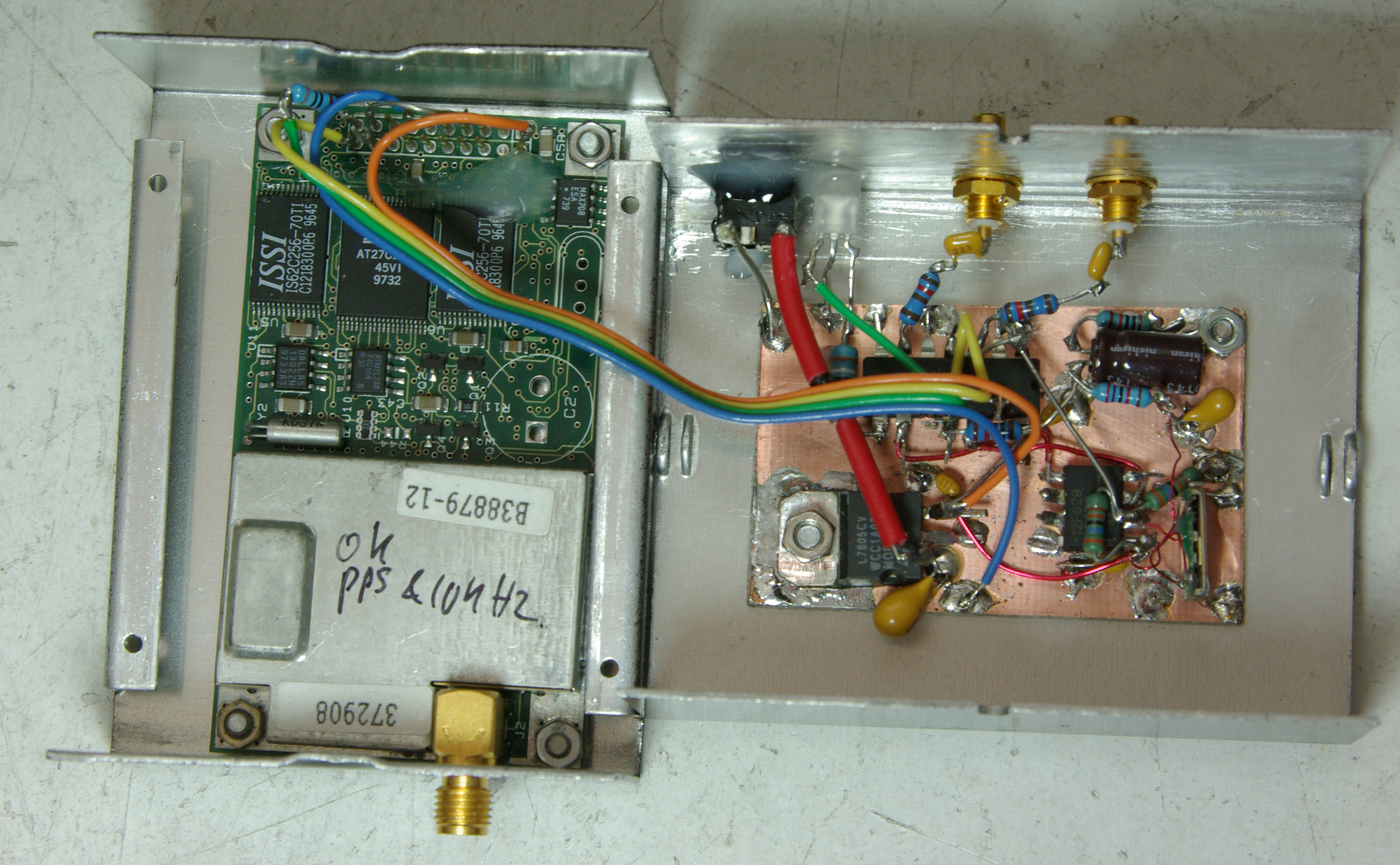
Instead of using a pair of HC390 chips to divide the reference down to 10kHz, this one uses a small 8 pin 12F629 PIC to do the job.
The PIC is clocked by the Reference (which is now a 20MHz VCTCXO as one was to hand). A few lines of PIC code generate a square wave at 10kHz which passes to the second chip, a 74HC86 exclusive OR, where it is compared with the 10kHz signal from the GPS module. The PIC also generates a quadrature 10kHz signal which goes to another XOR gate to drive a LED so that when the PLL is locked the LED is at either maximum or minimum brightness. The lockup process can be observed as it fades in and out.
The two remaining XOR gates in the chip can be used as buffers for outputting the clock signal
Different clock frequencies are possible within limits, by changing the division ratio in the 'Delay' routine in the PIC code.
Calculate the new value as follows (refer to EvenSimplerGpsdo.asm ):
PIC clock = Fin / 4
The main code loop takes 20 clock cycles (remembering 'goto' takes two) plus four calls to 'Delay'
The 'Delay' routine, including the call and return, generates 5.N + 5 clock cycles delay.
So for a 20MHz input, Fclock = 5MHz. To generate 10kHz we need 500 clocks cycles total in the loop. 20 are used up in the main loop, so four calls to Delay must generate 480 clocks, or 120 each call. 5.N + 5 = 120 so N = 23 - hence the 'movlw d'23' command.
Which simplifies down to N = (Fin / 800000) - 2
For a 10MHz clock input, life isn't so simple. As 10MHz does not divide by 800000. The main loop will have to be padded out with additional nop instructions to give a residue divisible by four, remembering to apportion the nop commands equally spread around each of the calls to 'Delay'. A small amount of jitter due to different numbers of nop padding instructions generating unequal delay calls for each quadrature element will not be important, but always check, double-check and check again that the total delay is exactly equal to that wanted !If 10kHz is not generated then the whole thing will never lock up.
PIC firmware :
Object Code for 20MHz Input
Assembler code